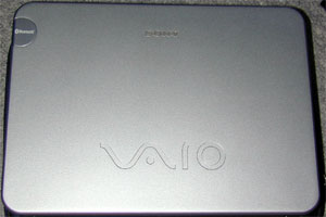
I have also tried to make a bluetooth upgrade to my parents SRX87,
and been thinking about how to do it for a while.
I got great help by snowwhite on this forum, and here it is how it is originally done, all information about the SRX7 is from him.
About SRX7’s bluetooth:

The bluetooth logo in the top left corner is hiding the bluetooth antenna in the magnesium chassi, also the bluetooth module is in the “screen” part of the computer.
Here is a very large (1mb) picture from the inside of a SRX7 with bluetooth:
Between the CPU and the cooler is a white connector, the grey cable from this connector goes through the right hinge nearby the yellow power plug.
There are a number of things that are “missing” in my SRX87,
compared to the SRX7:
* ALPS Bluetooth module
* Board that have antenna, and connector to the ALPS modul inside the screen
* Cable from the bluetoothboard to the main board
* Blue LED, and its driving components.
* Screen cover with whole in the magnesium chassie to let RF out.
As so much parts are missing, buying everything it too expensive and complicated
I went for the cheap and “easy” way, here is a quick/brief how-to.
Here is how I have done it so far (I havn’t completed it yet):
First I reverse engineered the (white) connector (connected to the grey ribbon cable), CN2603, and here is the pinout:
1 +5V
2 +5V
3 D- (USB)
4 D+(USB)
5 GND
6 GND
7 BT enable (logic line, HI(3.3V)=enabled)
8 Unknown, static lo (0V
9 Unknown, static hi while on (3.25V)
10 Unconnected
Any equpment can be connected to this “new” USB port, I successfully tried my mouse to this extra “internal” USB port.
The female part that fits the connactor is a JST part, art.nr: 10SR-3S
Datasheet:
I bought a normal bluetooth dongle, D-Link DBT-122, and took that apart:
I choosed that one because of it’s size, and that it could handle BT V1.2.
In my opinion the big difference between BT V1.1 and BT V1.2 is that BT V1.2 can avoid WLAN traffic if present. (if both parties have BT V1.2)
I also noticed at the picture on FCC’s website that it looked like it had a voltage regulator that could be used for power-off, unfortunantely that photo also showed that the unit had an PCB-antenna (just PCB tracks), typically low-cost, at the expense of range.
It works perfectly to just connect the DBT-122 to +5V, D-, D+ and GND in the connector, but as +5V is always present you must somehow turn the power off, othervise you will empty your battery.
Fortunantely it is possible as the regulator used on board the DBT-122 has an (unused) enable signal, that just need to be connected.
In the DBT-122 it is tied to +5V so the connection needs to be cut/disconnected in some way, either by lifting it’s “leg”, or by cutting a track.
If EN pin on the (similar/pin-compatible) regulator below is connected to pin 7 on the CN2603, the wireless off switch works as original
I use the same “Wireless Switch Setting Utility” as for my TR, and it works perfectly.
To get a nice blue light you have to place a blue LED (eg. Everlight EL19-21UBC), a resistor (150ohm) and FET transistor (any N-FET, SOT323) on the “botton-left” PCB inside the SRX, same PCB as the modular-telephone plug is mounted on.
I have desoldered the USB connector from the dongle and plan to place it in the ceiling inside the SRX87, next to the touchpad (on the right side of it, above the harddrive).
Everything is tiny with this mod, so and makeing a mistake shorting +5V into som 3V logic is probably very unhealthy for you SRX computer.
Use a stereo microscope while soldering, and double check your connections.
If anyone dare to follow my example I can make a more throgh how-to!
/Bushman